CG_Final : 2020级计算机图形学期末大作业
构建
项目地址:https://github.com/InverseDa/CG_Final
Windows
对于Windows用户,需要安装vcpkg:https://vcpkg.io/en/index.html
配置好vcpkg之后可以直接使用
1 | vcpkg install glfw assimp |
之后使用cmake构建(推荐用Visual Studio的MSVC)
1 | cmake -DCMAKE_TOOLCHAIN_FILE=<path\to\vcpkg>\scripts\buildsystems\vcpkg.cmake -B . -G "Visual Studio 17 2022" |
构建完毕后打开sln文件即可
Arch Linux
对于Arch Linux用户,需要用pacman安装glfw和assimp
1 | sudo pacman -S glfw assimp |
安装后在项目根目录下使用
1 | cmake -B .; make |
接下来将可执行文件设为可启动
1 | sudo chmod +x CG_Final |
最后执行即可。
技术细节
1. 延迟渲染管线
本次大作业摒弃了简单的前向渲染,采用基于帧缓冲的G-Buffer。这样,最终的输出就是由G-Buffers合成后的贴图,这样的性能就更高,因为在摄像头视线以外的片元不渲染。具体过程如下:
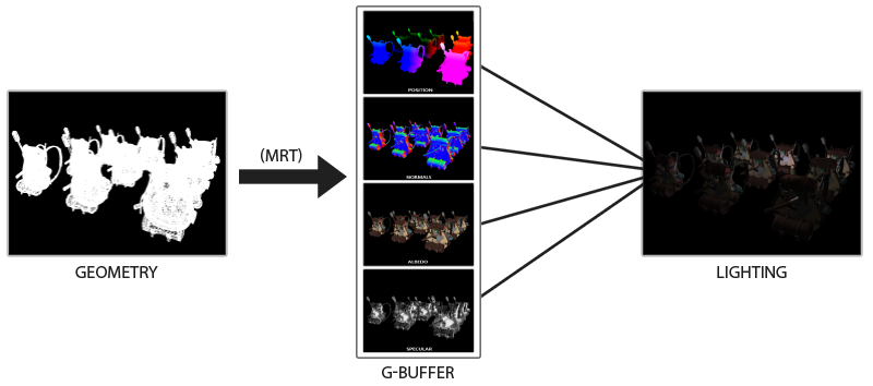
先将所有的片元按照以往的方式渲染,但这次并不输出颜色FragColor,而是将纹理信息、位置信息、高光信息和法线信息存储到四张贴图。这个过程叫做G-Buffer。也就是我们把原有的渲染方式通过G-Buffer输出到四张贴图中。最后,通过后处理技术,再进行渲染。
这样的好处是我们将所有的信息都存到了贴图中,这样最后渲染的时候,不重要的信息就不会渲染了。优化了性能。这个技术广泛应用在各种游戏中。但坏处就是,在延迟渲染中Blend就失效了。为了渲染透明物体,我们应当适当的将延迟渲染和前向渲染结合在一起。
我们专门用来G-Buffer的着色器统一用gbuffers_xxx.vsh/fsh来命名,而后处理统一用compositex.vsh/fsh来命名,本大作业的shaders文件结构大致如下:
1 | ./shaders: |
为了实现这个技术,我们需要用到OpenGL中比较强大的帧缓冲(Frame Buffer)来实现G-Buffer,这个帧缓冲将输出四张贴图。
1 | class FrameBuffer { |
这样就创建了一个帧缓冲类,可以利用这个类创建一个G-Buffer。
1 | FrameBuffer* gbuffer; |
因为我们采用的是指针开辟内存,所以用完需要回收内存空间。
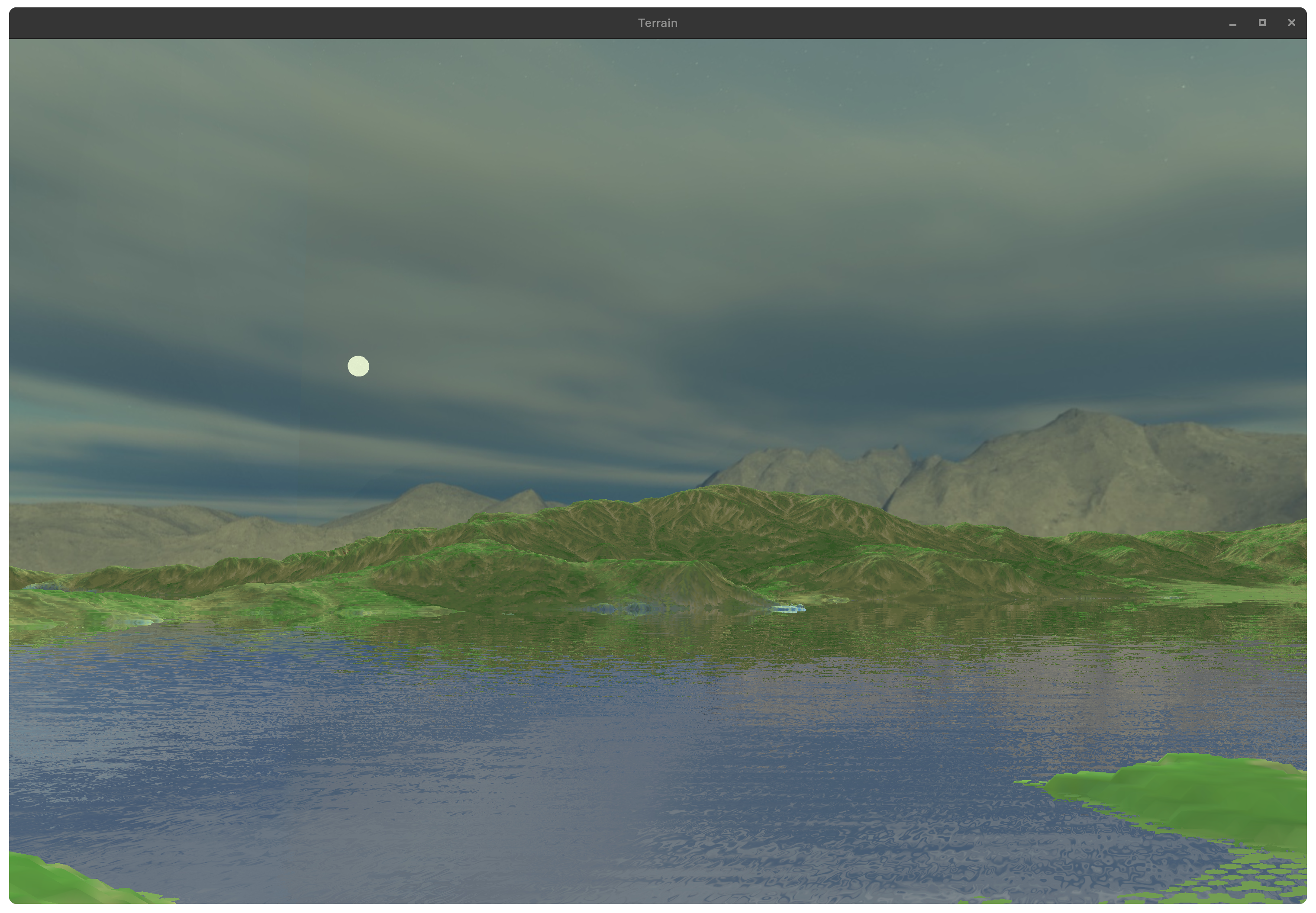
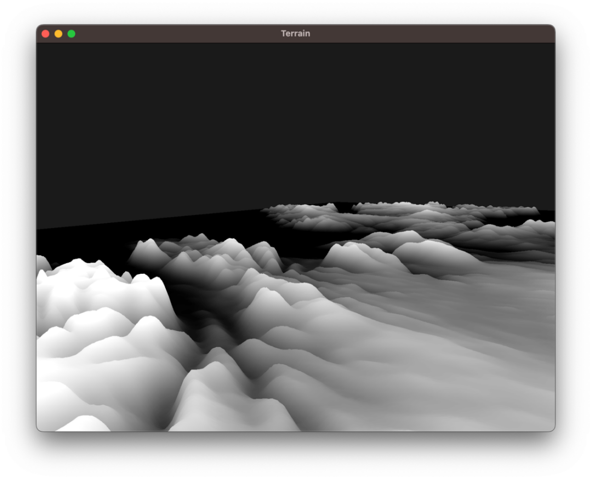
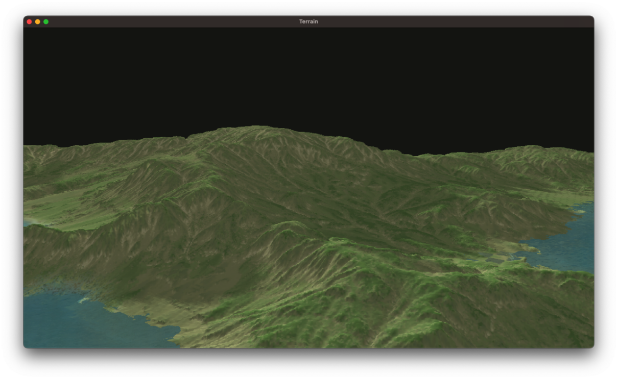
2. 基于CPU计算和高度图的地形生成算法
高度图一是张黑白的贴图,其颜色属性代表的含义是越黑即对应的片元y轴越小,越白即对应的片元y轴越大。通过渲染一张高度图,就可以生成对应的地形。因为这个算法是在CPU计算出来的,所以叫做基于CPU计算和高度图的地形生成算法。这个算法的时间复杂度是$O(n^2)$,但由于地图不大,并且一旦生成完毕便不再执行,所以在一定的地图规模下,这个算法还是相对优的。
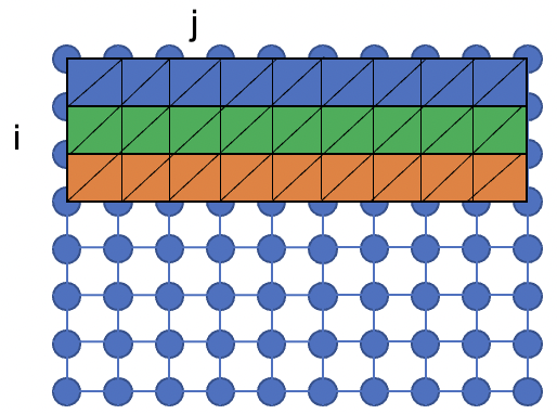
对于任何一张贴图,其数据结构都是二维数组。基于这个理论,我们可以得出高度图的大致结构:
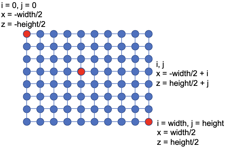
左上角就是高度图的左上角,其他位置都是同理。
我们以高度图的中央作为坐标系的原点,左上角为-x和-z方向,右下角为x和z方向。高度图中每个元素的值就是海拔的值y。所以我们通过读取高度图的值,就能确定这个地形的所有信息。
1 | int dwidth, dheight, dn; |
为了优化性能,我们需要做切片。也就是利用Element Buffer来定义面片切片。这里给出一种方法:
从正序的方向遍历(即先i后j),组成如上图所示的三角面片。为了达到这样的效果,可以按照这样的顺序构造面片:
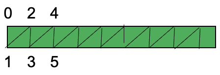
我们可以按照012345的顺序存储切片序列,这样012是一个三角形,345是一个三角形…推广至任意位置的:
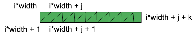
注意到我们没有渲染123,234的三角形,这是因为这样可以优化算法,避免多次计算。因为012和345可以合成一个矩形,在误差允许范围内这是可行的。
绘制方式如下:
1 | glActiveTexture(GL_TEXTURE0); |
注意到,我们之前还顺便传入了地形中每个顶点的UV坐标:
1 | ... |
因此,可以通过UV来进行地形的颜色绘制,着色器如下:
1 | // ======== VSH ======== |
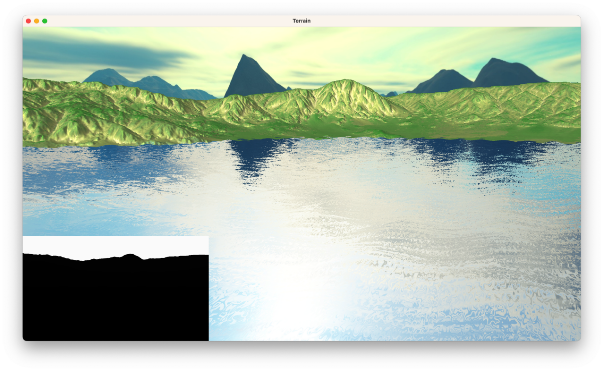
3. 阴影映射和PCF软阴影
定义一个专门渲染阴影的帧缓冲,然后先以光源为视角渲染出一张灰度的深度贴图。给阴影上色的时候先判断当前深度和深度图的深度大小,如果小的话说明需要上阴影,于是涂黑。这是最基础的阴影映射部分,为此我们先定义一个阴影映射所使用的帧缓冲:
1 | void initDepthMap() { |
其中shadowMapFBO是阴影映射时所用到的帧缓冲,我们以光源为视角,作向量$\vec{v}=\vec{0}-\vec{sun}$,以$\vec{v}/|\vec{v}|$ 为光源视角,绘制ShadowMap(或者说Depth Map)。
在绘制的时候,我们应当启用深度检测,因为我们需要生成一张带有深度信息的深度图,具体绘制代码如下:
1 | void renderDepthMap() { |
ShadowShader如下:
1 |
|
因为我们不对绘制任何片元,只是在shadowMapFBO的缓冲区下(不可见)的时候绘制深度图,所以只需要传递坐标信息即可。
其中,MVP变换矩阵中$\bold{lightSpaceMatrix}$ 的值如下:
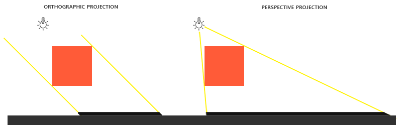
而投影矩阵我们采用正射投影而不是透视投影。这是因为正交投影矩阵并不会将场景用透视图进行变形,所有视线/光线都是平行的,这使它对于定向光来说是个很好的投影矩阵。然而透视投影矩阵,会将所有顶点根据透视关系进行变形,结果因此而不同。
而基本的阴影绘制思路如下:
1 | float ShadowCalculation(vec4 fragPos) { |
PCF是优化阴影的一种方法,因为这种方法所获得的阴影可能会由于ShadowMap的分辨率而存在质量问题,比如锯齿阴影。
PCF在获得阴影的颜色之后,再做加权平均。也就是说从深度贴图中多次采样,每一次采样的纹理坐标都稍有不同。每个独立的片元可能在也可能不再阴影中。将这些结果加权平均,我们就得到了PCF阴影。
1 | float ShadowCalculation(vec4 fragPos) { |
其中textureSize返回一个shadowMap的0级mipmap的vec2类型的宽和高(Lod)。用1除以它返回一个单独纹理像素的大小,我们用以对纹理坐标进行偏移,确保每个新样本,来自不同的深度值。这里我们采样得到9个值,它们在投影坐标的x和y值的周围,
为阴影阻挡进行测试,并最终通过样本的总数目将结果平均化。
4. 环境贴图
环境贴图用于构建天空盒,这样可以极大的提高场景的美观。需要注意的是,环境贴图最好是静态的,另外我们希望天空是“触不可及”的,所以需要去除位移因素,使得天空永远相对于人不动。
1 | void initSkyBox() { |
创建天空盒需要用到正方体,所以最好我们能够手动输入坐标、法向量和UV坐标。
另外还需要加载环境贴图:
1 | unsigned int loadSkyBox(std::vector<std::string> &faces) { |
5. 动态水
水我们可以简单理解为一个平面,这个平面我们可以细分成很多小的三角面片,这样我们就可以随意操控这个平面内的任意遵循三角面片关系下的坐标。
对于细分部分,我们由下面的代码可以解决:
1 | const int WATER_VERTICES_HEIGHT_AND_WIDTH = 410; |
我们根据WATER_VERTICES_HEIGHT_AND_WIDTH,创建了WATER_VERTICES_HEIGHT_AND_WIDTH * WATER_VERTICES_HEIGHT_AND_WIDTH的水矩阵,每个矩阵的元素都是一个顶点。对于UV的计算,我们是采用hashMapx来进行分配,这样保证水面中每个小正方形(两个三角面片)能显示一张水贴图。(后来发现,因为我们要用环境贴图反射的颜色来覆盖水面,那么这个UV就没啥必要了……)
绘制代码如下,因为使用索引存储,所以绘制代码很简单:
1 | glBindVertexArray(waterVAO); |
(1) 利用最简单的波函数创建动态水
一个简单的波函数由三角函数叠加:
其中$x,y,z$ 为水面每个三角面片的坐标,对于单个顶点坐标而言,这个方程表达了水顶点的高度$y$ 随水平方向两个坐标$x,z$ 和世界时间$t$ 的具体关系。
我们可以用顶点着色器实现:
1 |
|
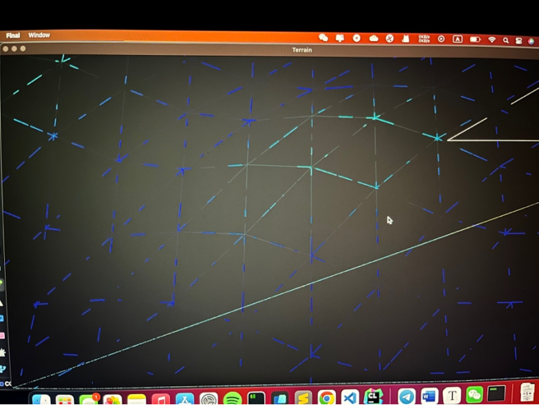
其中worldPosition就是顶点的世界坐标,debug模式中能清晰看到波动效果。
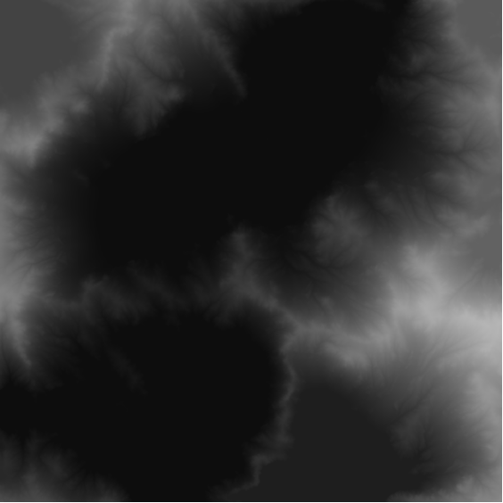
(2) 噪声图生成水波
为了方便期间,我们可以使用现成的柏林噪声图,将其导入:
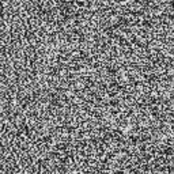
导入后可见:
1 | float getWave(vec3 pos) { |
将波纹合成到最终颜色里:
1 | vec3 tex = vec3(texture(waterTexture, fs_in.TexCoords)); |
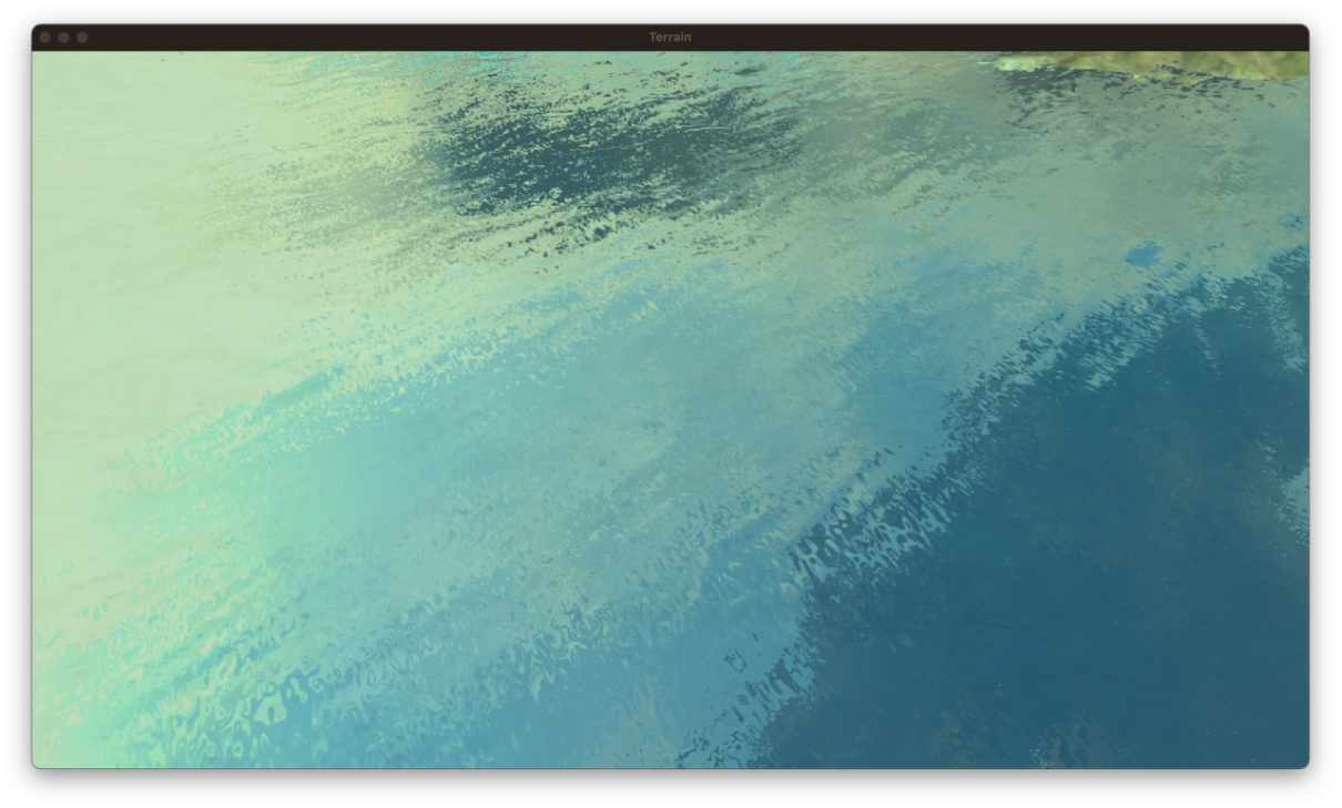
(3) 环境映射
我们可以给水增加环境贴图的颜色,这样会显著提高真实感。由于天空盒的环境贴图UV是三维的,所以可以用三维的反射向量来取色,另外,可以让法向量随着波纹扰动,这样映射后的颜色也是来回变化的:
1 | vec4 reflectSky(float wave) { |
直接拿来使用,就可以得到相对真实的水:
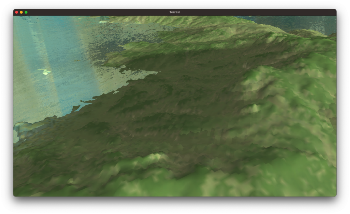
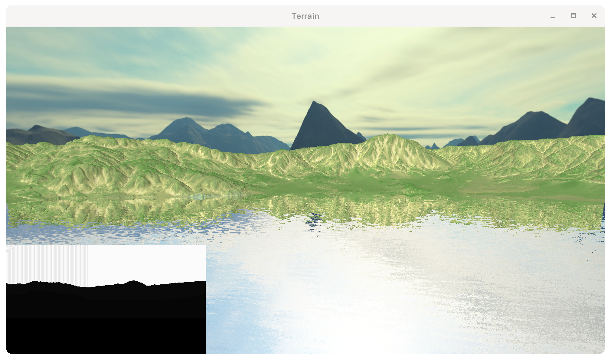
(4) Screen Space Reflection
屏幕空间反射是一种后处理算法,这个算法需要在延迟渲染管线中执行,常用于写水面的反射。
其思路是在后处理的过程中,所有片元都在相机空间下运算颜色,并且最后在NDC空间内取色(充当UV)。
取水面某个世界坐标点P,将P变换到相机坐标下:
将$\bold{P’}$ 单位化,就可以得到从相机(人)到该点的相机空间下的入射向量,记作$\bold{T=P’/|P|}$。根据该顶点的法向量,可以得到反射向量$\bold{T’}$。
以水面的顶点为起点,往反射向量的方向叠加。如果当前顶点碰撞到了世界的片元,那么就算反射成功,取碰撞点的颜色,赋值给水面。
1 | float maxRayDistance = 100.0f; |
而rayMarch主体:
1 | vec3 rayTrace(vec3 rayPos, vec3 dir, int iterationCount) { |
CG_Final : 2020级计算机图形学期末大作业
http://blog.inverseda.top/2023/03/04/ComputerGraphics/CG_Final/